WA4GEG Notes; FT-1000MP Mark-V series
FT-1000MP Mark-V (200 watt)
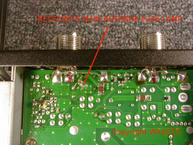
WA4GEG's Receiver Antenna FUSE LAMP mod. (Tuner-Main update)
FT-1000MP Mark-V (200 watt version): The T/R switching circuitry is
known to fault under certain conditions, most commonly when
transmitting into high SWR, open circuit, faulty antenna system,
and improper use of the ATU. The unfortunate end result is
multiple component destruction on several circuit boards.
The addition of an antenna fuse lamp (pictured below) in the
receiver's main antenna signal path will save $$$ in repair
costs. In the event of the afore mention faults the fuse-lamp
will burn open effectively disconnecting the antenna path to,
and protect from destruction, the receiver's front-end (RF Unit Board)
and the receiver's vacuum-reed T/R antenna relay.
This modification (or the Micro-Fuse mod; see Note below) was
automatically applied to all Mark-V's serviced in my shop for
decades. The fuse-lamp will also burn open and protect the receiver
front end from dangerously high RF levels from a nearby transmitter,
high power mobile unit, proximity lightning, etc.
NOTE: An alternative to the soldered in place "fuse-lamp" has
been applied to many Mark-V rigs for those without soldering
skills, or that simply prefer a plug-in replacement solution. On those
rigs a plug-in micro-fuse was fitted in place of the "fuse-lamp", the
LittelFuse p/n 0273.125 spec'd at 125 mA, the version with 5mm leads.
Spares are available for order @ $5.00 each + $2.00 postage. To order replacements
contact: wa4geg [AT] gmail [DOT] com and type MICRO-FUSE in the subject line.
DIY detail: Not visible as it is under
the lamp, the copper foil circuit path between the lamp's two
solder points is opened / cut.
Lamp specs; low power (about 1/2 watt) with up to a 14 volt filament. For lowest loss on 10 meters (receiver antenna path) my preference is to use 5 to 6 volt grain-o-wheat lamps with a 0.100 (0.125 max.) ampere filament rating when using just a single lamp, or 0.050 to 0.060 ampere filament when using a pair of lamps wired in parallel.
FT-1000MP Mark-V; ICAS 200 watt PA & Class-A Cautions
FT-1000MP Mark-V series transceiver's User Menu Settings
To enhance SSB
transmit audio the DSP may then be engaged. Suggested settings
are as follows: 4-4
Transmit audio EQ
3 MIC GAIN control:
With a good quality microphone, preferably a headset mic. for
excellent VOX operating characteristics, a properly align
FT-1000MP series transceiver will require no more than a MIC
GAIN setting of 9 o'clock. Most often a setting between 8 and 9
o'clock is all that is required to attain ALC metering peaking
toward the upper ALC scale limit. PROCessor level
control: When the speech processor is activated, a PROCessor
level setting of no more than 10 ~ 11 o'clock will achieve
excellent results without over compressing transmit audio into
distortion. (Compression level peaking 3 bars on the COMP
metering scale. -- assuming that the transceiver is in good
alignment) *SNR = Signal to
Noise Ratio. The lower the SNR, the better the weak signal
reception, assuming low noise conditions etc.
Many an operator has fried the final stage output RF power MOSFET (transistors) by using the Mark-V
PA's (Power Amplifier) Class-A mode as a convenient way to limit TX-PO to 70 watts for key down antenna tuning and etc.
Long duration Class-A operation (key down time) results in very serious overheating of the final stage transistors,
guaranteeing premature breakdown failures in very short order. I.e. key down Class-A, with no RF power output, biases
the final stage MOSFETs' to 300 watts DC input power, which translates to 300 watts of continuous heating, a level
of heating that can not be conducted from the transistor's die to the aluminum heat sink fast enough to prevent transistor
breakdown. This is not a cooling fan issue, rather the ICAS heat sink design, which does not have the recommended integrated
copper heat spreader. Those who get by running Class-A, are those who operate SSB VOX Break-in with very short VOX delay
(hold) times. However, the astute operator and those with very thin wallets, would do well in completely avoiding the
use of Class-A for any purpose.
To get the most service life out of the Mark-V's 200-watt ICAS (Intermittent Duty Cycle) RF Power Amplifier,
history has proven these recommendations: Use 200 watts PEP or less for SSB voice, 100 watts or less for CW taking
care to limit "tuning up" keydown time to no more than 5 seconds (when running 100 watts output). Use 50 watts maximum
AM/FM carrier power for short "break-in" transmissions, 25 watts AM/FM carrier power for long-winded transmissions,
25 watts max. for short burst transmissions on digital modes (10 watts for long time-frame transmissions).
200 Watt PA MTBF service life example: I know contest operators that manage to get from 10 to 15 years out of a set
of "finals" (RF power MOSFET output transistors) while other operators with a "heavy foot" manage to blow their finals
after only a year or two. On the other hand, others have over 18 years on the original set of finals in their Mark-V
(200 watt) transceivers, operating only SSB voice at 100 watts power output.
In the course of servicing, and to properly align these
transceivers, it is necessary to set certain user menus as
follows. These settings also give the highest analog operating
performance for the transceiver, including the best receiver *SNR
for all bands 160 through 12 meters. (For best 10 meter *SNR, set menu 8-4 to tuned.)
4-4 TX Audio DSP EQ
OFF
5-0 (only for **Mark-V &
Field) OFF (OFF = 2.4 KHz
filters ON, as odd as it seems)
7-7 EDSP modulation and
demodulation OFF, OFF, OFF, and OFF
8-4 Front End RF Amp
Selection FLAT
8-9 Carrier Offset
All ranges
set to all zeros
7-7 SSb-t
150 ~ 3100 (Hz)
**I commonly find menu 5-0 set to 8.2 - 455 in many Mark-V and
Mark-V Field transceivers. This "mal-setting" defeats the
internal 2.4 KHz crystal filter when the filter selection
BANDWIDTH is set to the NOR position. The 2.4 KHz filter is
available when the BANDWIDTH NAR-1 is selected however. Such a
menu "mal-setting" makes it appear as if the transceiver has a
narrow option filter installed at position NAR-1, which is
normally reserved for the 2.0 KHz option filters (when in SSB
mode.) And more importantly, performance suffers in that the
receiver's IF circuitry is exposed to adjacent frequency
interference. Such a menu setting is useless for serious SSB/CW
work, and should be avoided - unless perhaps you have an after
market narrow roofing filter installed (i.e. Inrad Roofing
filter) and desire listening through the 5 KHz nominal
bandwidth of the after-market "roofer."
FT-1000MP Mark-V, Linear Power Supply
Replacements for the dual voltage FP-29:
For the 30-VDC requirement, a 28VDC linear power supply is an excellent
choice, provided the Mark-V is operated at 150 watts maximum SSB PEP output,
yet again an excellent idea for increasing the service life of the "final"
RF output MOSFET/transistors.
Power supplies fitted with a front panel current limit adjustment may be
set for 16 ~ 18 amperes of limiting, which is not critical since the
Mark-V itself has internal current limiting (ALC) for its 200 watt PA Unit.
One supplier for 28 VDC linear power supplies is Astron, which manufactures
rugged RFI quiet "aka noisless" linear regulated classic "heavy iron"
transformer based units, and one of particular interest is their model LS-18A.
Details available on Astron's website here:
http://www.astroncorp.com/28vdc-linear-desktop
For the 13.5 VDC requirement, use a regulated supply rated for at
least 3.5 amperes, continuous duty.
Wiring:
The Mark-V DC power cord is then wired as follows. WARNING, observe correct
polarity and correct connections to prevent damage to equipment!
Connect to the 13.5 VDC power supply:
Small ORANGE wire to (+) Positive
Small GREEN to (-) Negative
Connect to the 28 VDC power supply:
Large RED wire to (+) Positive
Large BLACK wire to (-) Negative
Small white wire: no connection
Small gray wire: no connection
Note; The Mark-V will be fully functional on receive when powered from
the 13.5 VDC supply.
Once the transceiver is up and receiving, activate the 28 VDC
power supply to enable operation of the transmit section's 200-Watt PA Unit.
ATU / Antenna Tuning Unit & Outboard Tuner Cautions
How-to reduce the risk of damaging your FT-1000MP Mark-V series transceiver from its
internal antenna tuner, or as some refer to it, auto-tuner:
1) Keep menu 4-3 (TUNING DRIVE) set for no more than 50 watts of power (75W for the 200 watt Mark-V.)
2) Always measure your antenna's SWR before activating the internal tuner, i.e. RF Power set for about 10~20 watts, CW
mode, and PTT your mic. and read the SWR on the transceiver's meter. Practice has shown that the tuner has difficulty handing
non-resonate systems and an SWR close to or greater than 2.5:1, especially so with the 200 watt FT-1000MP Mark-V. Attempting to
tune an out of range or otherwise non-tunable loads risks damage to T/R, ATU and expensive RF power amplifier components.
3) FT-1000MP Mark-V 200 Watt ATU; The topology of the design places the Auto Tuner Unit between the 200-watt PA and the
QSK-T/R circuitry & ANT-A/B switching. In other words, the ATU only matches the 200-watt PA while everything else
down-line (the Mark-V's QSK-T/R circuitry & ANT-A/B relays) will remain subjected to the station's feedline VSWR. There are
advantages and disadvantages to this topology.
Disadvantage; Consider the case where a 2:1 SWR is presented by the antenna system, and the ATU is activated to match the 200 watt PA into the 2:1 SWR enabling full TX PO into the load. However, the 2:1 SWR remains present at/on the QSK-T/R & ANT-A/B areas of the circuit, and the components in those circuits must then deal with either higher than normal (200 watts into 50 ohms) RF voltage levels or higher RF current levels, owing to whether the 2:1 SWR is on the Hi-Z or Low-Z side of 50 ohms.
This is the Achilles heal of the design, the ATU will match certain loads that are dangerous to the health of the components in the QSK-T/R circuitry, risking destruction of those components. Many an operator has made the mistake of activating the Auto-Tuner's tune cycle into the incorrect antenna or an empty antenna coax jack, aka "open circuit" often with destructive results. To make matters worse, the now 18+ year old servo-driven ATU are failing intermittently and causing an increasing number of damaging "tuning faults". The commonly reported failure symptoms are high SWR with and without the ATU inline, loss of receive audio / RF sensitivity, loss of transmit output, most if not all of these --indicating a trip to the repair shop is in order.
In the interest of preserving the service life of the 200 watt Mark-V, it is highly recommended: DO NOT USE THE INTERNAL AUTO-TUNER. USE AN OUTBOARD TUNER where a tuner is necessary. This can not be stressed strongly enough. Yaesu no longer has the "proprietary parts" for the Auto-Tuner Unit thus rendering it non-renewable. All Mark-V rigs ship from my shop with the ATU set to "off" in user menu 8-8. ACTIVATE AND USE THE AUTO-TUNER AT YOUR OWN RISK, ITS YOUR RADIO. And be advised,"IF YOU ARE GOING TO PLAY, YOU ARE GOING TO HAVE TO PAY" sooner or later.
5) OUTBOARD TUNER WARNING: The 200 Watt FT-1000MP Mark-V is not bullet proof! Use extreme care when adjusting outboard antenna tuners. Most operators assume that it is safe to set the Mark-V for a low transmitter output power, and then wildly crank the knobs around on their outboard antenna tuner. Not a good idea! Such an incorrect technique is known to strain the Mark-V's QSK T/R switching. The QSK T/R switching is known to fault in certain situations, resulting in the destruction of components.
When adjusting external tuners the better method is to use an Impedance Bridge, such as one of the commonly available Antenna Analyzers, to find and log all adjustments for each band of interest. Thereafter the adjustment log is used as a guide to preset the tuner's controls to the proper range BEFORE transmitting a low power carrier to tweak the tuner. Following this method allows the impedance presented by the TUNER to the Mark-V to be within operating specifications of the transceiver's protective circuitry.
ROLLER INDUCTOR TUNERS are the most troublesome of all outboard tuners. The maintenance factor aside, high power "hot tuning" roller inductors is a concern for solid state transmitters. The problem being that the continuity of the aging roller inductor's moving electro-mechanical components seldom remain optimum, particularly while the roller is in motion. SWR spikes occurring while tuning roller inductors is a known cause for damaging solid state transmitters, to say the least.
Back to Main Page
The content on this site is protected by copyright. All rights reserved.
©HamRadioBug.com