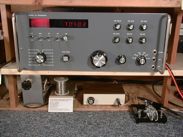
The main station Solid State SSB/CW HF
transceiver:
Construction on this rig began in the early '80s and finished (almost) by 1990.
The front panel is 17" x 7", attached to a 3"x 17" x 12" chassis for lots of elbow room. The transceiver covers all
HF amateur radio bands from 160 through 10 meters and operates modes QSK-CW and VOX-SSB + AM receive. Circuit info:
Single conversion (+23 dBm diode ring front-end mixer) into twin hybridized crystal roofing filters, then standard
selectivity filters (all at 9 MHz I-F) with 100 dB receiver agc range using a pair of MC1350 IF amp. ICs',
direct digital frequency display, high stability VFO controlled tracking-loop (PLL) LO system, and
all solid state QSK diode T-R antenna switching.
The S-meter is illuminated with red LEDs' to match the frequency
display red LEDs', and very easy on the eyes for late night DX chasing on 160m:
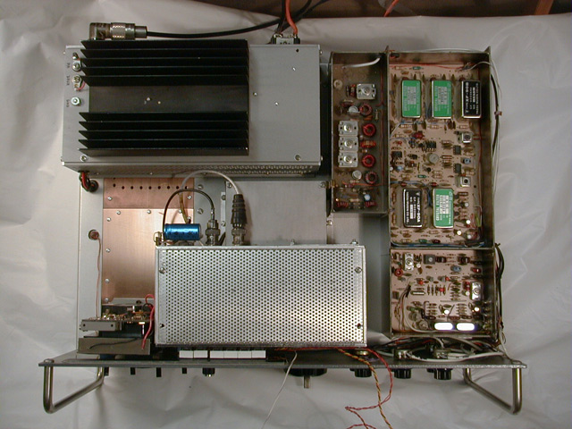
A look inside; top view. Center bottom; F-Display Unit sitting atop the PLL shielded
enclosure. Right bottom section; TX Bal. Mod. w/ speech amp. and USB/LSB BFO crystal oscillators. Above
(larger section) contains RX IF Amps. w/ main and tail-ending xtal filters, IF derived AGC, SSB/CW Product
Detector and AM detector. Large box w/ heat sink: detail below. Note: those wires dangling out of view go
to the Noise Blanker board; removed for better view of the RX IF Section.
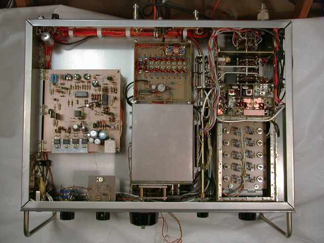
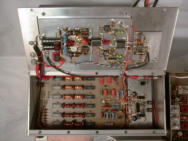
A look inside; bottom view. Square box at center bottom is the VFO. Above
it is the TX Mixer Unit containing a double-balanced mixer IC: MC1496, pre and post amps. (2N3866) and
band-pass filters (diode switched.)
Right chassis and extending from front to back (or top to bottom in this view)
is the band switch section; bottom section and working up are the VCO Unit, RCVR Front End diode mixer
section containing twin roofing filters and post amplifier. The section above this contains the two-pole RCVR
front-end Preselector. Following it is the switch section that band switches via DC control voltage the
transmitter low pass filters, transmitter mixer band-pass filters, PLL down-mix HET OSC and
VCOs'.
Left chassis main board contains RCVE Audio, VOX, ALC, SWR Protection,
AVR and T-R Control circuitry:
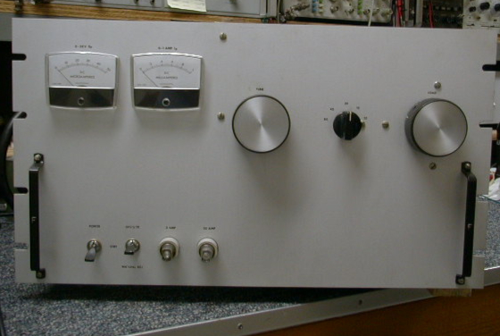
Power Amplifier Unit hinged out of it's shield box; Power transistor
line-up: 2SC1306 predriver, push-pull MRF476 driver and push-pull MRF455 final stage. The larger bottom
pc board contains the SWR Bridge, dip-reed relay switched Low Pass Filters and Diode T-R Antenna Switch.
The smaller bottom pc board contains bias control circuitry for the power amplifier final and driver stages:
* Page updated 09/31/2022
Back to HamRadioBug.com index page*This page was constructed with Bluefish, powered by FreeBSD (Unix) and is best viewed in 1024 x 768 or higher resolution.
The content on this site is protected by copyright. All rights reserved.
©HamRadioBug.com